Probably the most important tool in the maker's toolbox is the multimeter. Multimeters can be used to help diagnose pretty much any part of your circuit. Most multimeters can test for the 3 most common variables in a circuit: voltage, current, and resistance, and you can use these measurement in an Ohm's Law Calculator. Understanding how to use a multimeter is important for everything from testing batteries and fuses, to diagnosing component and circuit failures. Lets start by looking at the multimeter itself.
Understanding the Multimeter’s Front Panel
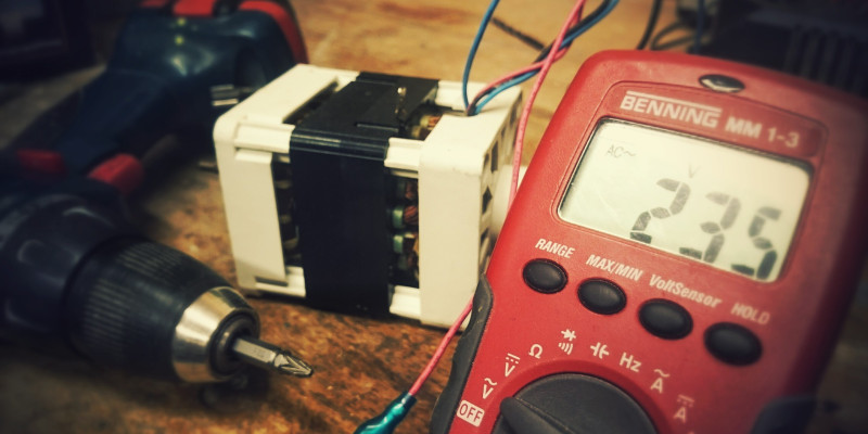
All digital multimeters have 3 things in common – a display, a rotary dial, and test lead ports. Although different multimeters may have different features, all multimeters share this design.
The multimeter display is usually an alphanumeric LCD display featuring 4 digits, a decimal point, and a negative sign. A few high-end multimeters have a display with more digits, and an illuminated screen for when you are in a dark environment.
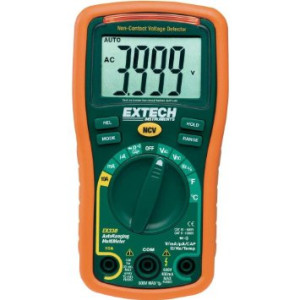
The selector dial allows you to switch the multimeter between multiple operating modes. There are various options for resistance, current, and voltage (both AC and DC). For each mode in a standard multimeter, there are multiple options to change the precision. For example, you may choose between 20A, 200mA, 20mA and 2mA. If you set the dial to the relevant mode, the display can adjust and show you the required precision. Some multimeters are auto-ranging, meaning that you only have to select the test mode, and the display will adjust to the correct measuring range.
The test lead ports are where you connect your test probes. The black lead is connected to the COM port (which stands for common), and is used to connect to the ground of a circuit. The red probe is connected to the mAV****Ω port, and is connected to the positive of the circuit. Most multimeters also feature another port for testing high current circuits, which is usually labelled as 10A. These probes are a standard size and are called banana connectors. The most commonly used probes have a long thin needle that can be accurately placed in a circuit, but there are other types available such as crocodile clips.
Using a Multimeter to Test Voltage
A word of warning: the circuits you use with Arduino and Raspberry Pis are usually low voltage, low current DC circuits. Your home uses a high voltage, high current AC circuit. Don’t mess around with AC unless you know what you are doing. That means don’t stick your multimeter into the power sockets in your wall!
Multimeters allow you to test for the voltage in AC and DC currents. The different selections are indicated via different symbols. AC is shown using a tilde symbol (~)and DC is shown using a straight line, with a dotted line beneath. For most projects you are going to want to use the 20V DC option. This will allow the multimeter to test accurately up to 20V, with a precision of 2 decimal places. If you are measuring less than 2V (such as an AA battery), you can select the 2V option. This will allow you to test with 3 decimal places of precision. If you choose an option that’s too low for your test, you will get an error message (or a 1) – simply adjust the range to suit.
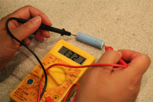
As a test, let’s use a multimeter to test a battery. For this, grab an AA or AAA battery from your junk box (everyone has a junk box!), and set your multimeter to the 2V option for testing. As a fully charged AA/AAA battery has a nominal voltage of 1.5V, this is the best option. Connect the red probe to the positive side of the battery (+), and the black to the negative (-) by pressing the needles to the edges of the battery. You should see your multimeter display showing a voltage. If it’s a new battery, it may show around 1.6V, and if it’s used, it may get down to 1.3V. Using the probes the wrong way round isn't a problem - the display will show a negative symbol, which is handy for checking which way round a circuit is!
Measuring the voltage of any DC circuit works in the same way - you use the black lead to ground, and the red lead to the voltage you want to test. If you want to measure the output of a potentiometer, or a sensor, simply connect the black probe to the ground pin, and the red probe to the data pin. Potentiometers and sensors (the ones which don’t use a serial connection) will vary the voltage output between 0V and the input voltage (usually 5V or 3.3V).
Next, take out your Arduino board and power it up in your preferred way. Now, connect the probes to the 5V pin, and the GND pins. If you have thick probes that don’t fit in the pin sockets, don’t force them! Make a note of which pin is which, and connect the probes to the solder blobs underneath. You should get a reading of around 5V. It will probably show slightly above this voltage – don’t worry, there’s always a slight margin of error either in the multimeter or the voltage regulator on board the Arduino.
Using a Multimeter to Test for Continuity
One of the most important tests a multimeter can check for is continuity in the circuit. If your circuit doesn’t work, but everything looks OK, then checking for continuity at the various components is the first step.
Continuity testing works by checking the resistance at 2 different parts of a circuit. If there is hardly any resistance detected between the probes, there must be an electrical flow. If this is the case, the multimeter will make an audible noise. Some lower end multimeters may not have a continuity feature. Some multimeters rely on the display to show continuity, rather than use a beep sound.
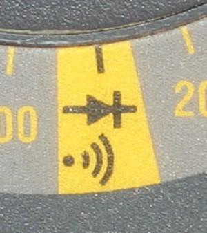
First, set your multimeter to the continuity test setting. This will be a symbol of a diode, and may also feature a symbol of sound waves. Touch your 2 probes together and you should hear the beep. Now we know it’s working, we can go about testing circuits.
Lets try testing with a wire. Probe both ends of the wire, and you should hear a beep. In the highly unlikely even that you don’t, this means the wire has broken somewhere inside the plastic sheath. If you have a breadboard, you can try the same on this. Probe between two points in a row, or down the ground or power rails, and you should hear the beep.
With a lot of switches, it’s difficult to work out whether it is open. Continuity testing can help check whether a switch is on or off, and can help when you want to mount the switch in a panel in a specific orientation. If you are using a basic toggle (single-pole single-throw latching) switch, simply probe the 2 pins of the switch. If you hear the beep, the switch is on, and if you don’t the switch is off.
It’s also simple to use a multimeter to check a fuse using the continuity checker. Probe both sides of the fuse. If the fuse is working, then you will hear the beep. If you fuse has blown, you won’t hear the beep and it’s time to replace the fuse!
Using a Multimeter to Test Resistance
The most often use for the resistance test mode, is for checking a resistor’s value. If don’t know how to calculate the resistor’s colour codes off the top of your head, you will have to use some sort of calculator to work out its value. A much quicker way is to grab your multimeter and test it!
If you set your multimeter to the 20kΩ mode, and probe the two ends of the resistor, the actual resistance in ohms will display on the screen. If your display shows OL (or just a 1), then the resistance is higher than 20kΩ, and you need to set your resistance test range to the next highest on the dial. If the display shows a zero (or almost zero), then you have a resistor with a small resistance that can’t be displayed, and you should adjust the range to a lower value.
If you try this on a resistor that you know the value of, you will probably notice that the value shown on the display is slightly different than the value of the resistor. This is due to the tolerance allowed in the design. Most resistors have a 5% tolerance, meaning that the actual resistance can be +/- 5% of the rated value. There are other factors that can skew results, such as the temperature, humidity, and nearby components (if already in a circuit).
Using a Multimeter to Test Current
A word of warning: With most multimeters, the positive probe port you use to check voltage and resistance can be used to check up to 200mA of current. A small circuit won’t use this much power, so you should be fine using this. If, however, you think that the current may be above 200mA, you should use the 10A port. Multimeters have an internal fuse, and if you push more current than it can handle, it will blow! Another thing to remember is to not directly connect positive and ground while in current mode. This will short the circuit, causing all the power to flow through the multimeter and again blow the fuse!
Detecting current is done in a different way to other tests – the test must be done in series rather than parallel. This involves physically breaking the circuit, and changing the flow of electricity to go through your multimeter.
For an example, lets say we want to test the current a simple circuit uses. The circuit is a battery, an LED and a resistor. Now we need to connect the multimeter as if it were a component in this circuit. First we disconnect the wire between the positive of the battery, and the next component (either resistor or LED). We then probe the positive of the battery with the red probe of the multimeter, and then probe the component with the black probe. If you are using a bread board, you can use the probes to connect from the positive voltage rail, to the row containing your first component.
We have now connected our multimeter in-line, and the flow of electricity will go battery positive -> multimeter -> LED -> resistor -> battery negative (or similar depending how you have connected your circuit). Remember how we said at the beginning you can get crocodile clip probes? This is where they come in handy! This will be a bit cumbersome trying to do with standard probes, so using the clips to grip the components makes life a lot easier.
Once the circuit is complete, the LED should light up and the multimeter will start to show the circuit’s current. The current shown on the display is shown as an average over a short time. It’s best to not rely on the current being precise, as the circuit may fluctuate slightly. If you are testing your Arduino, for example, the power consumption may fluctuate based on what the sketch is doing at the time.
Conclusion
Multimeters are an invaluable tool in your toolbox. We’ve written a post looking at the best multimeters for every budget if you are stuck on what to buy. Even a cheap multimeter will open up a world of help in troubleshooting circuits. It’s always advised to get the best multimeter you can afford, as if you get a good multimeter, you won’t need to buy again for years to come, and it should have all the features you need. Happy making!